Encoder with PIC MPLAB IDE (예제1)
Naver
pic16 예제
http://www.circuitvalley.com/2012/10/rotary-encoders-interfacing-pic18-avr.html
Rotary Encoder Interfacing with PIC Microcontroller
 Rotary Encoder PIC18.zip
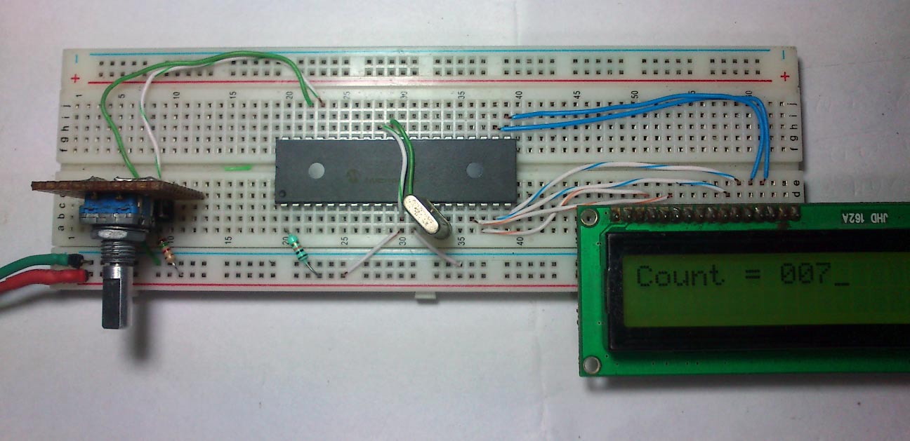

Source code 는 총 3개로 나뉘어 있다.
lcd16.h lcd16.c main.c
우선 봐야할 것은 lcd16.h이다.
이 안에있는 #include <p18F458.h>
#include <delays.h>역시 주목해야한다.
 p18f458.h
▼▼▼▼▼lcd16.h▼▼▼▼▼▼▼▼▼▼▼▼▼▼▼▼
#ifndef __lcd16_h_
#define __lcd16_h_
#include <p18F458.h>
#define RS PORTCbits.RC3 //정의한다. RS를 포트C3로
#define EN PORTCbits.RC2 //정의한다. EN을 포트C2로
void numToLcd(unsigned char); //lcd16.c안의 method참고
void gotoXy(unsigned char ,unsigned char); //
void lcdInit(void);
void lcdCmd(unsigned char);
void lcdData(unsigned char);
void lcdWriteNibble(unsigned char);
void waitLcd(unsigned char);
void prints(const rom char * message);
#endif
▲▲▲▲▲▲▲▲▲▲▲▲▲▲▲▲▲▲▲▲▲▲▲▲▲▲
▼▼▼▼▼lcd16.c▼▼▼▼▼▼▼▼▼▼▼▼▼▼▼▼▼▼▼▼
#include "lcd16.h"
void lcdCmd(unsigned char Data) //4번 메소드
{
EN=0;
PORTD =((Data >> 4) & 0x0F);
RS=0; //because sending command
EN=1;
waitLcd(2);
EN=0;
PORTD = (Data & 0x0F);
EN =1;
waitLcd(2);
EN=0;
}
void lcdData(unsigned char l) //5번 메소드
{
EN=0;
PORTD =((l >> 4) & 0x0F);
RS=1; //because sending data
EN=1;
waitLcd(2);
EN=0;
PORTD = (l & 0x0F);
RS=1; //because sending data
EN=1;
waitLcd(2);
EN=0;
}
void lcdInit(void) //3번 메소드
{
RS=0;
EN=0;
PORTD= 0x3;
waitLcd(40);
EN=1;
EN=0;
waitLcd(5);
EN=1;
EN=0;
waitLcd(5);
EN=1;
EN=0;
waitLcd(2);
PORTD=2;
EN=1;
EN=0;
lcdCmd(0x28); //set data length 4 bit 2 line
waitLcd(250);
lcdCmd(0x0E); // set display on cursor on blink on
waitLcd(250);
lcdCmd(0x01); // clear lcd
waitLcd(250);
lcdCmd(0x06); // cursor shift direction
waitLcd(250);
lcdCmd(0x80); //set ram address
waitLcd(250);
}
void waitLcd(unsigned char x)
{
unsigned char i;
for (x ;x>1;x--)
{
for (i=0;i<=110;i++);
}
}
//gotoXy(column, row);
void gotoXy(unsigned char x,unsigned char y) //2번 메소드
{
if(x<40)
{
if(y) x|=0b01000000;
x|=0b10000000;
lcdCmd(x);
}
}
void prints(const rom char * message){ // Write message to LCD (C string type)
lcdCmd(0x8); // disable display;
while (*message){ // Look for end of string
lcdData(*message++);
}
lcdCmd(0xE); // enable display;
}
void clearLcd(void)
{
// Send command to LCD (0x01)
lcdCmd(0x01);
}
void numToLcd(unsigned char num) //1번 메소드
{
lcdData((num/100)+0x30);
lcdData(((num/10)%10)+0x30);
lcdData((num%10)+0x30);
}
▲▲▲▲▲▲▲▲▲▲▲▲▲▲▲▲▲▲▲▲▲▲▲▲▲▲
▼▼▼▼▼main.c▼▼▼▼▼▼▼▼▼▼▼▼▼▼▼▼▼▼▼▼
/*
* File: main.c
* Author: Gaurav
*
* Created on September 2, 2013, 11:49 PM
*/
#pragma config OSC = HS, OSCS = OFF //configuration settings
#pragma config PWRT= OFF , BOR=OFF, BORV = 27
#pragma config WDT = OFF
#pragma config LVP =OFF , STVR =OFF
#include <p18f458.h>
#include "lcd16.h" //includes the lcd routines header file,
//the rotary encoder is not dependent on this
//but in this demo required to display.
#include <delays.h> //C18 compiler delay routine header file
/*
* 관련자료 링크
* Delay1KTCYx :: Delay multiples of 1000 Tcy
* Delay1TCY :: Nop()
* Delay10TCYx :: 2560 cycles
* Delay100TCYx :: 25600 cycles
* Delay1KTCYx :: 256000 cycles
*/
#define REA LATBbits.LATB4 // Rotary encoder pin definition
#define REB LATBbits.LATB5 //정의한다. REB를 래치 B 비트들중.래치B5 라고
//C18 Header에서 LATBbits에 대해 정의되있다.
//Hi-Tech에서는 다르게 정의한다.
void pbchange(void);
//portb change routine this routine is being called by the interrrupt serivice routine on portb change interrupts
void callISR(void);
#pragma code highPI = 0x008 // to put the code on Interrupt Vector
void highPI(void)
{
_asm
goto callISR
_endasm
}
#pragma code
#pragma interrupt callISR //checks which one of the interrupt is occured
void callISR(void)
{
if(INTCONbits.RBIF==1) //check for PortB change interrupt
{
pbchange(); //call the routine
}
}
unsigned char count; //this variable will incremented or decremented on encoder rotation
void main() {
TRISD = 0x00; // set the PORTD to output
TRISC = 0x00; // set the PORTC to output
TRISBbits.TRISB4=1; // set rotary encoder pins to input
TRISBbits.TRISB5=1;
lcdInit(); // inilized the LCD
prints("Count = ");
numToLcd(count); // display count to lcd
INTCON2bits.RBPU =0; // enable pullups
INTCONbits.RBIF = 0; // clear the interrupt flag
INTCONbits.RBIE = 1; // enable PORTB change interrupt
INTCONbits.GIE = 1; // enable the global interrupt
while(1)
{
}
}
void pbchange(void )
{
unsigned char state;
static unsigned char oldstate; // this variable need to be static as it has to retain the value between calls
Delay1KTCYx(5); // delay for 1ms here for debounce
state= REB<<1 | REA; // combine the pin status and assign to state variable
if(oldstate==0x0){
if( state ==0x1)
{
count--; //decrement the count
gotoXy(8,0); //goto proper position on the LCD screen
numToLcd(count); //display the count value on to LCD
}else if( state == 0x2)
{
count++; //decrement the count
gotoXy(8,0); //goto proper position on the LCD screen
numToLcd(count); //display the count value on to LCD
}
}
oldstate = state; // store the current state value to oldstate value this value will be used in next call
PORTB = PORTB; // read or Any read or write of PORTB,This will end the mismatch condition
INTCONbits.RBIF = 0; // clear the porb change intrrupt flag
}
▲▲▲▲▲▲▲▲▲▲▲▲▲▲▲▲▲▲▲▲▲▲▲▲▲▲